Application of Engineering Principles by Emmett Osborne
Posted on November 25, 2022 at 1:08 PM
Have you ever wanted to build something, but didn't know where to start? Follow along as I work through designing, building, and testing a complex robotics project and learn the basics of modern day Engineering Principles
The following is a timeline summary of approximately 4 months of development of a Tripedal Walking Robot. Currently, there have been 4 phases to this project. First, the non-functional concept. Second, the semi-functional prototype. Third, an itteration of the semi-functional prototype with increased functionality, and fourth, the current design.
Follow along as we progress through these phases of development and pay close attention to the lessons learned from each mistake. Behind every mistake, there is always a lesson to be learned.
Phase Zero - Non-Functional Prototype
Before spending hundreds of dollars on a concept that may not be possible, it is critical to verify that what you are attempting to build is at least physically possible, given the constraints you have given. The constraints on this project were originally defined as follows:
- Three legs
- 3 servos per leg
- Wireless (Battery Power)
- Wireless Remote Control
- Semi-Autonomous
- Unique Through Leg Gait
Almost all of these design requirements are knowingly doable. Tripods exist, so 3 legs shouldn'd be a problem. 6 axis control happens with 3 motors on gimble mounts, so 3 servos shouldn't be a limiting factor. Battery power is simple enough. So is wireless control. Semi-Autonomous isn't a cake walk but as long as the correct measurement tools are in place it becomes a software problem to be tackled in the future. The only one I could not gerentee was the unique gait I wished to accompish.
The only reference to this gait I could find was a research project out of UCLA called STriDER. This project was lead by Students and professors out of Virginia Tech, specifically Jeremy Heaston, Dennis Hong (more on him later!), Ivette Morazzani, Ping Ren, and Gabriel Goldman. The following 15 year old video is from that project. Note, the simulation at 3:13 is the only visual concept of this specific gait I have found on the internet.
Studying STriDER, I realized my functional requirements of 3 servos per leg did not overlap with their design. I had to make a non-functional prototype to make sure the concept I had in mind was possible. A weekend later, and this weird thing was born!

This simple but powerful hunk of plastic and magnets was able to demonstrate to me that the gait I was attempting to design for was possible with the 3 joints I was planning! Now on to phase 1.
Phase One - Semi-Functional Prototype
This next process took around a month. During the course of that month, I built a prototype remote control (still in use today), a servo testing system, a test system for some measurement tools, and a first plastic robot! The limbs were made of 3D printed plastic, and the first 6 servos were used. Below is an image of the plastic limbs, as well as a photo of the remote control.
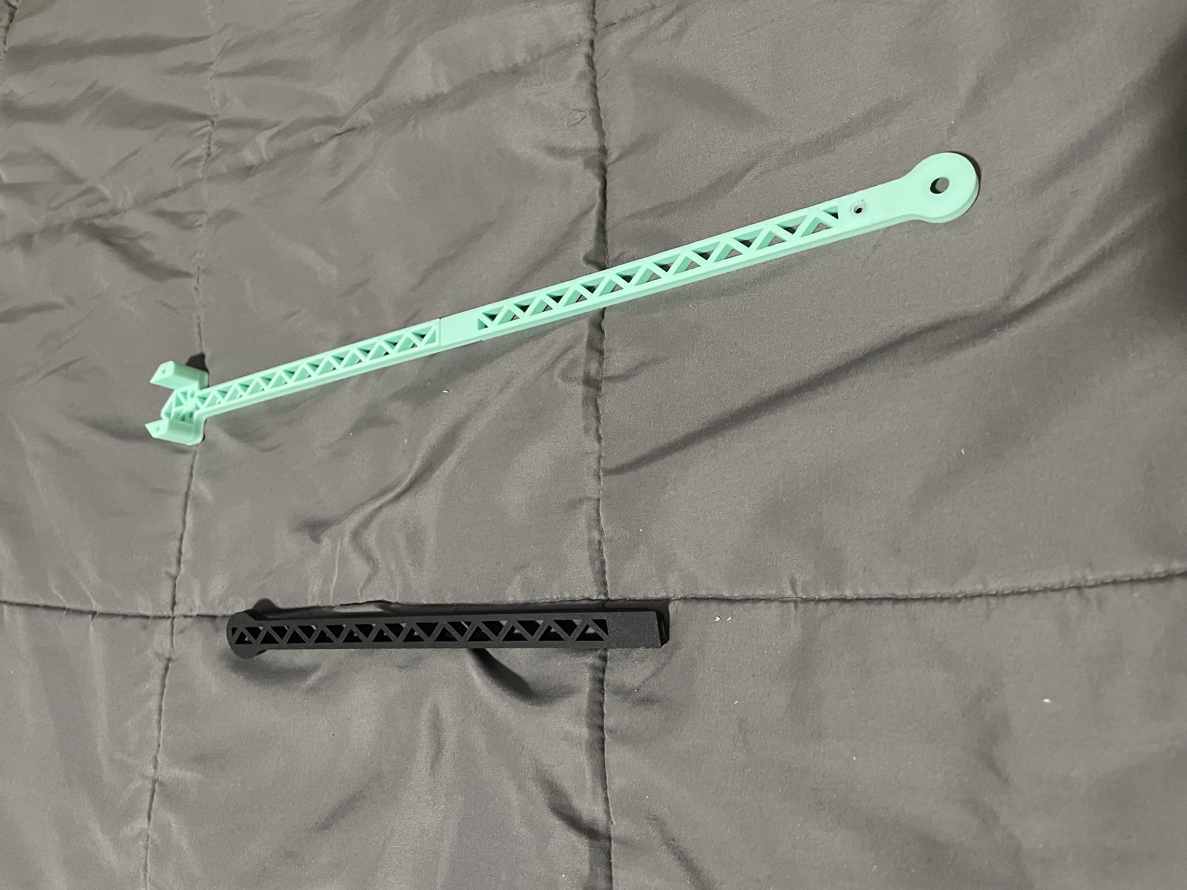
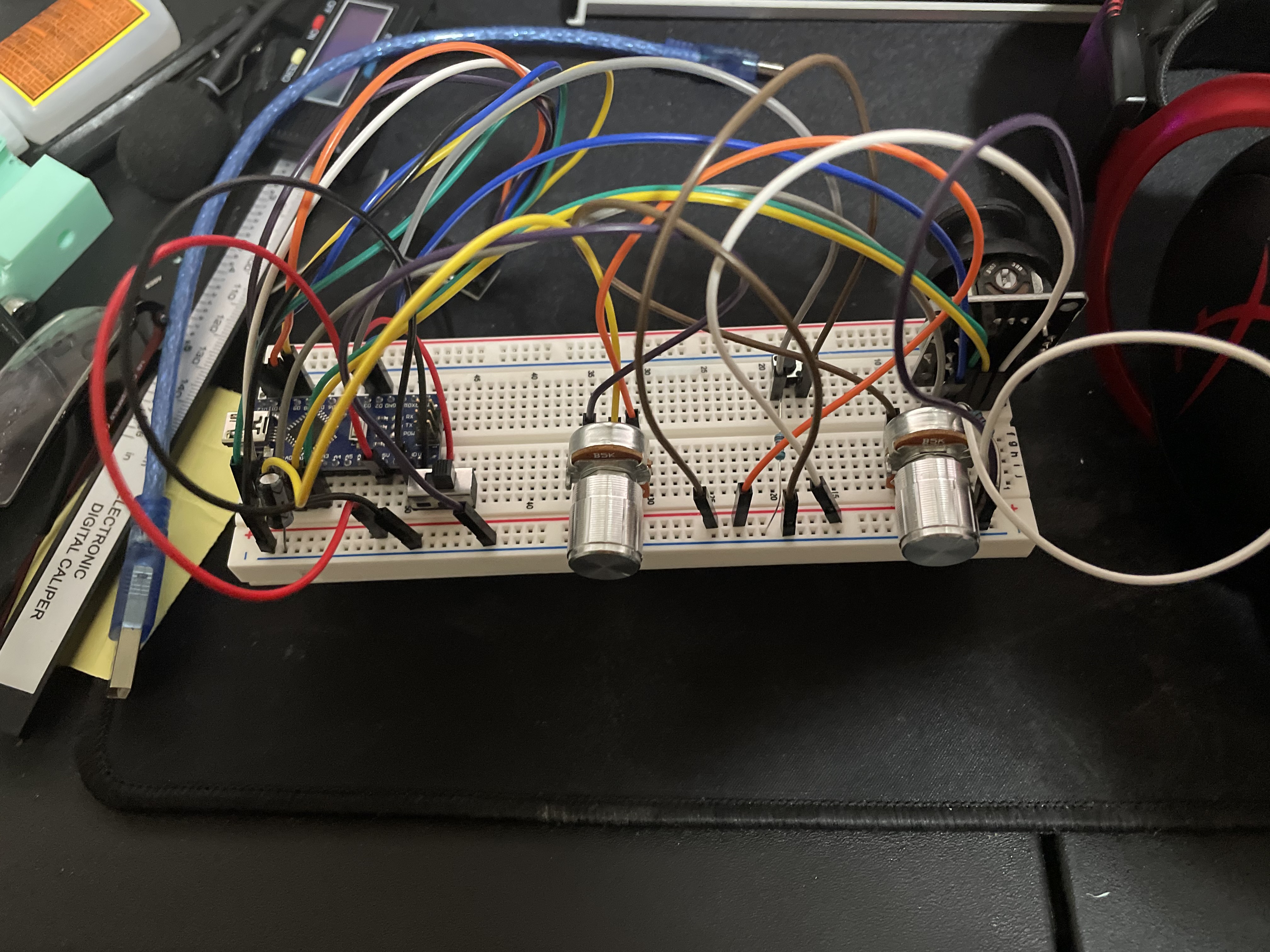
These designs helped solidify my confidence in the tripedal design, as well as taught me some important lessons. Let's review some. First, the plastic limb is too flexible! I would need something stronger. Two, the remote control circuit I built has FAR greater range than I anticipated. I would not need a fancy antana on either the robot on the controller. Great, now on to phase 2.
Phase Two - Better Semi-Functional Prototype
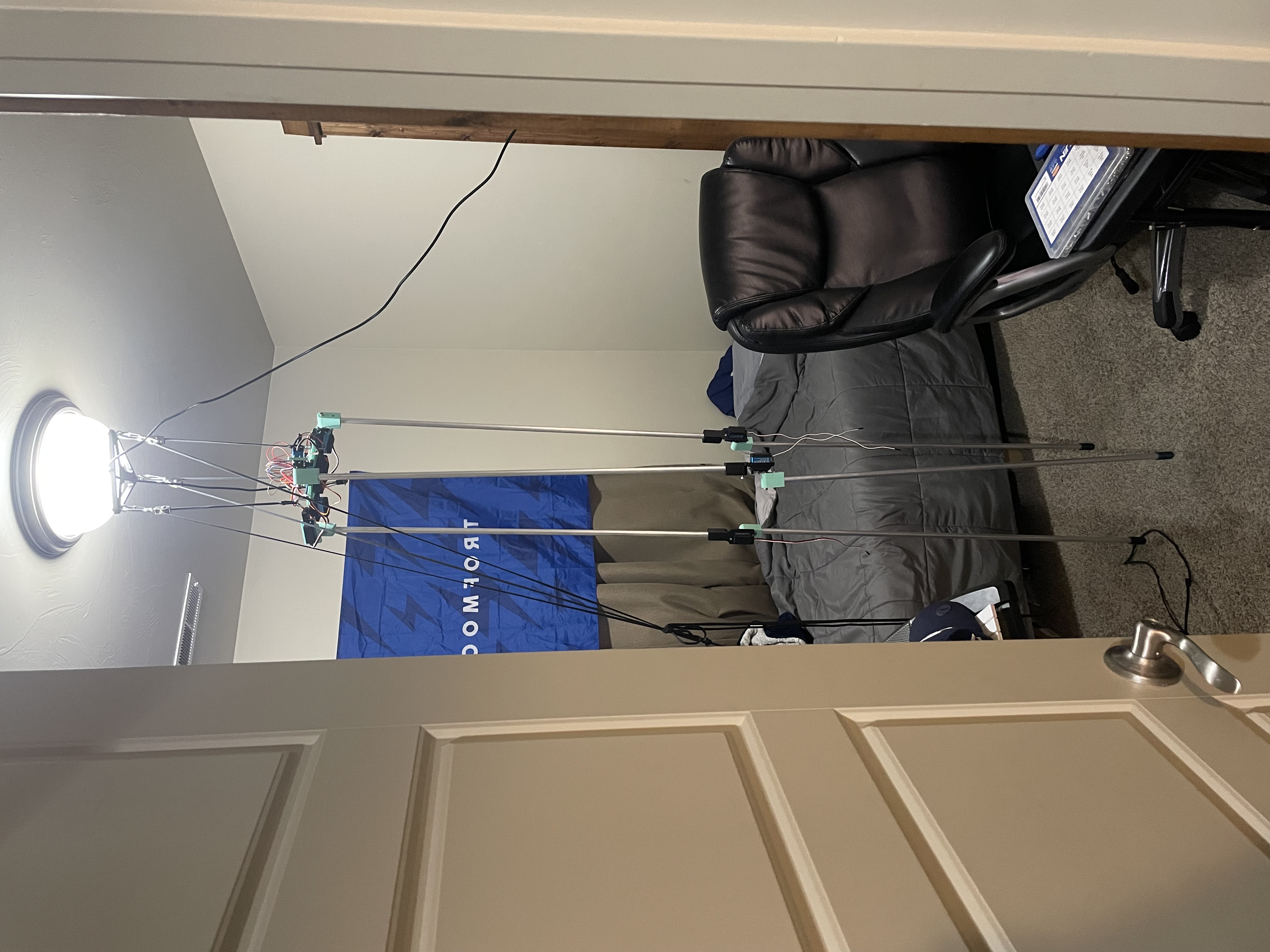
I present to you, how to work on a 7 foot tall robot in a very small room. Hang it from the ceiling! As long as my landlords don't find out, this setup allowed me to work on the lanky robot without taking up so much space.
It is worth noting that at this time I reached out to Dennis Hong on Twitter to see if I could get some insight into some of the design problems they may have encountered with STriDER. Fortunately, he chatted with me for quite some time and I was able to solve several problems I would have encountered ahead of time.
This newest design incorperated the changes learned from the previous design, most noably the aluminum legs. Unfortunately, this is also where the problems began! First, lets review some technical requirements I have yet to divulge.
- Servo Voltage: 6V-7.2V
- Battery Output Voltage: 7.2V-9V
- PWM Driver Voltage Limit: 6V
Notice a problem here? The PWM Driver voltage limit is lower than any possible voltage the batteries could output. During one of the first tests of this completed system, a combination of this high voltage and a bound servo lead to an electrical fire on the PWM Servo Driver!
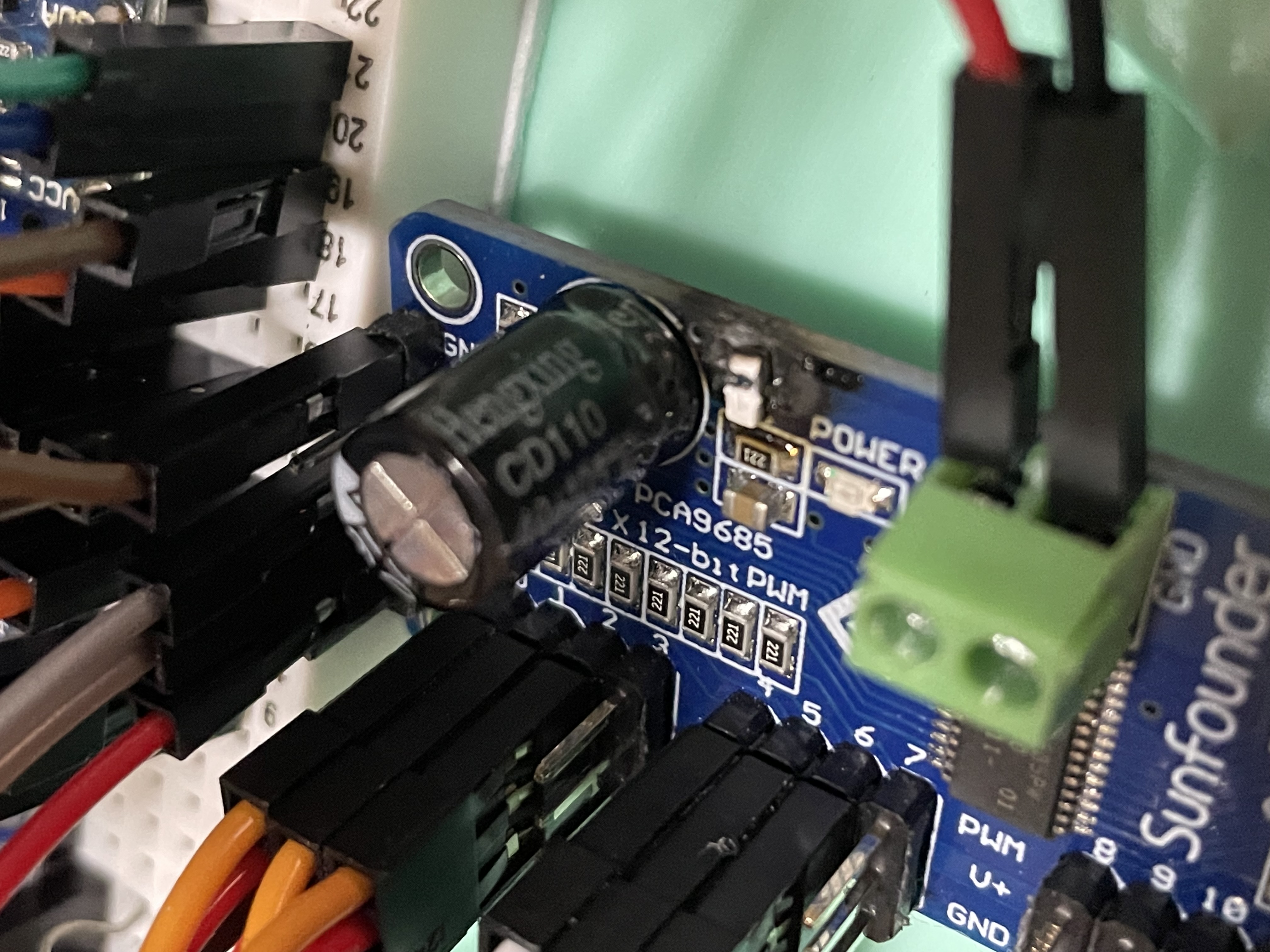
Not only did this set me back around $20, but this required a change in design. Looking at the design for the PWM driver board, the component that blew was a reverse polarity protection circuit that just couldn't handle the high voltage/current. I would need to bypass this circuit if I wanted to use this PWM board. Unfortunately, there was bascially no other options for PWM drivers, so I had to find my own solution. Luckily, this was relatively simple. So, what was the lesson learned here? Stated limits are important! You can break them, but don't expect to get away with it very often.
I am skipping quite a bit of development here, and I just wanted to emphasize how much. The photo below is a collection of pieces I kept during this development process. The vast majority I threw away.
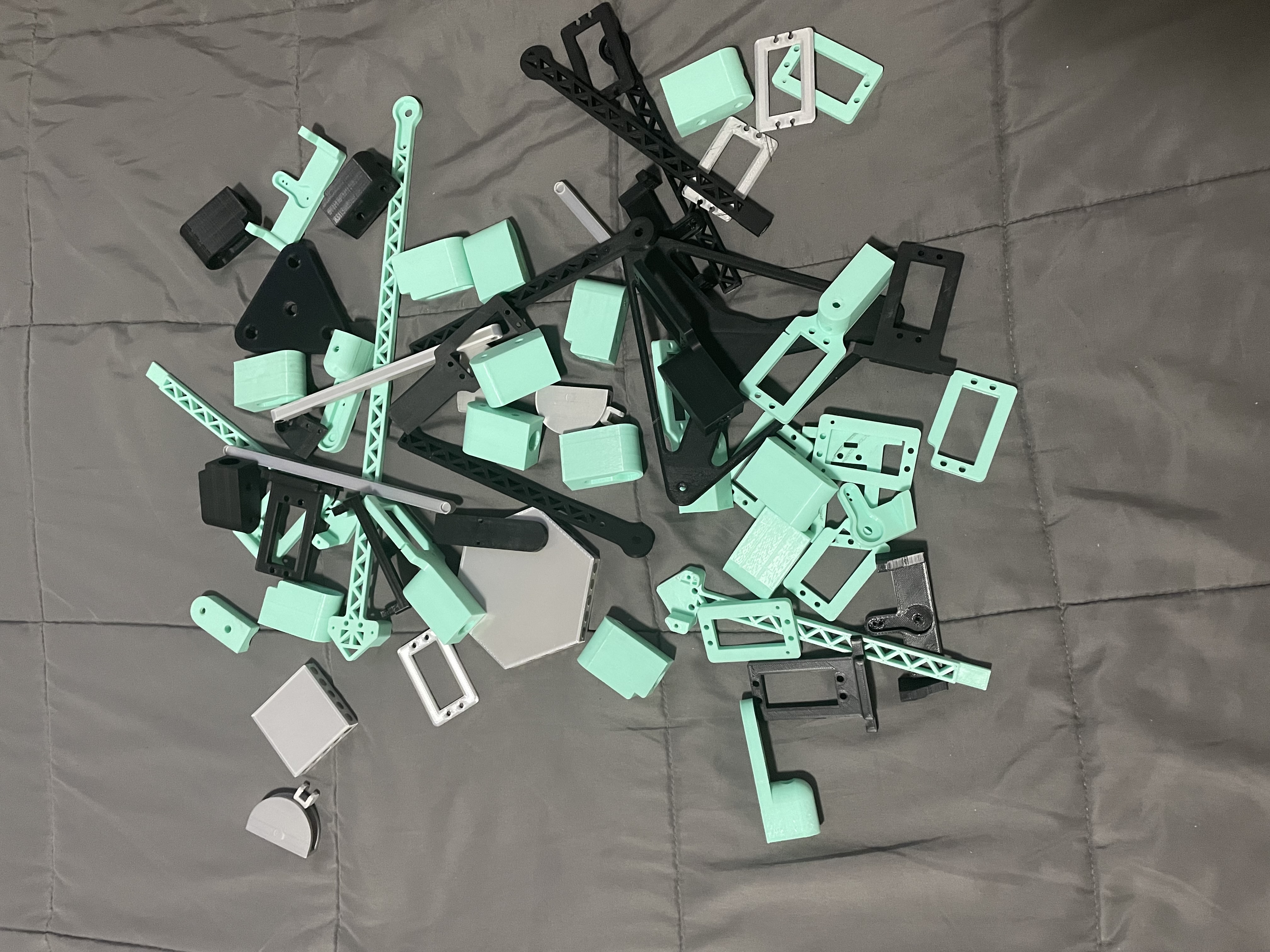
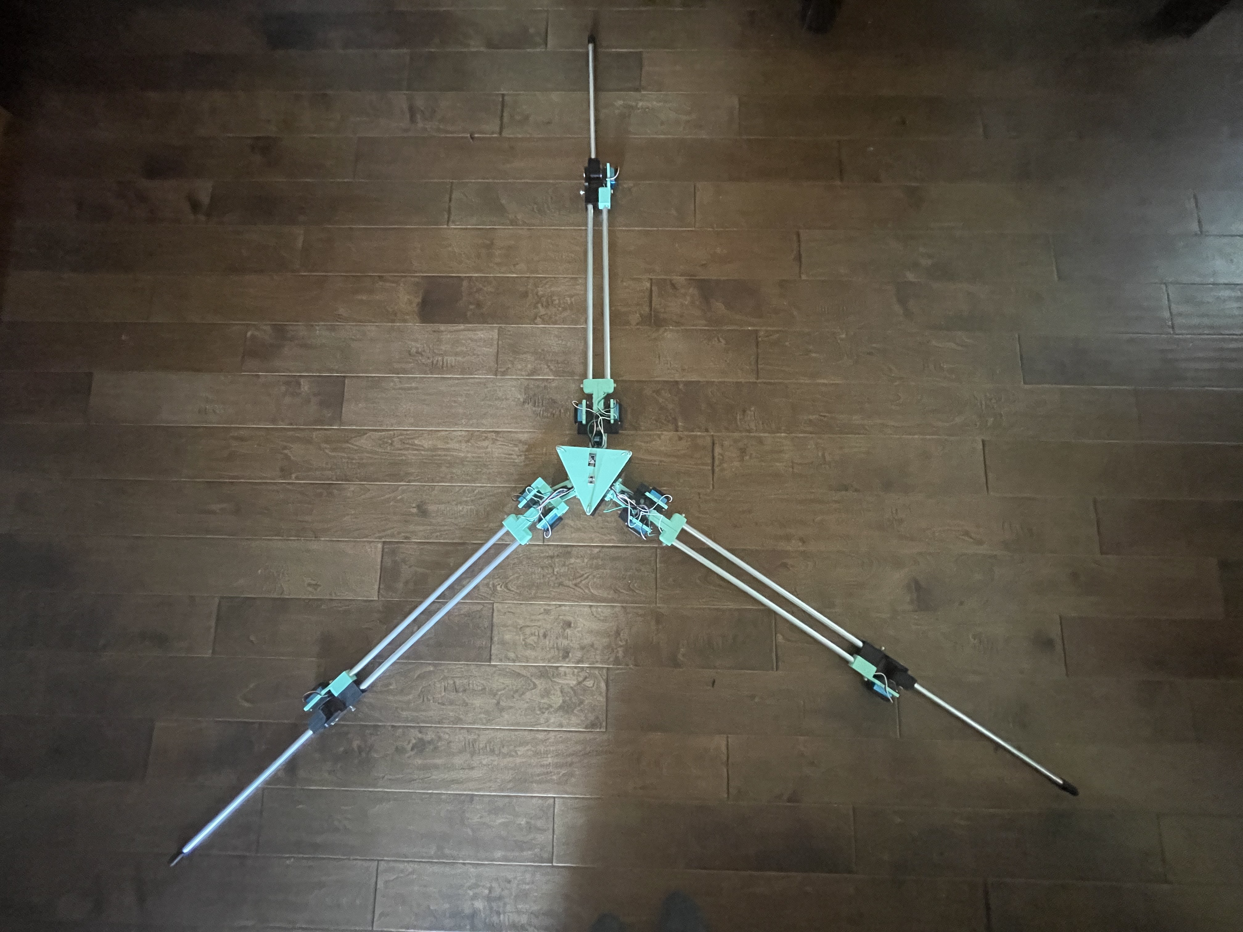
The vast majority of Phase 2 was design and redesign. Despite a few minor disasters, lots was learned and the design evolved respectively. So what was the specific reason why a Phase 3 was needed? Well that's simple, Phase 2 could not stand- at all. The design of the legs was not symetrical, and therefore not balenced. This meant that when the robot would attempt to support its own weight, the legs would just twist and the whole thing would collapse. The newest design (and current design) in Phase 3 fixed this problem.
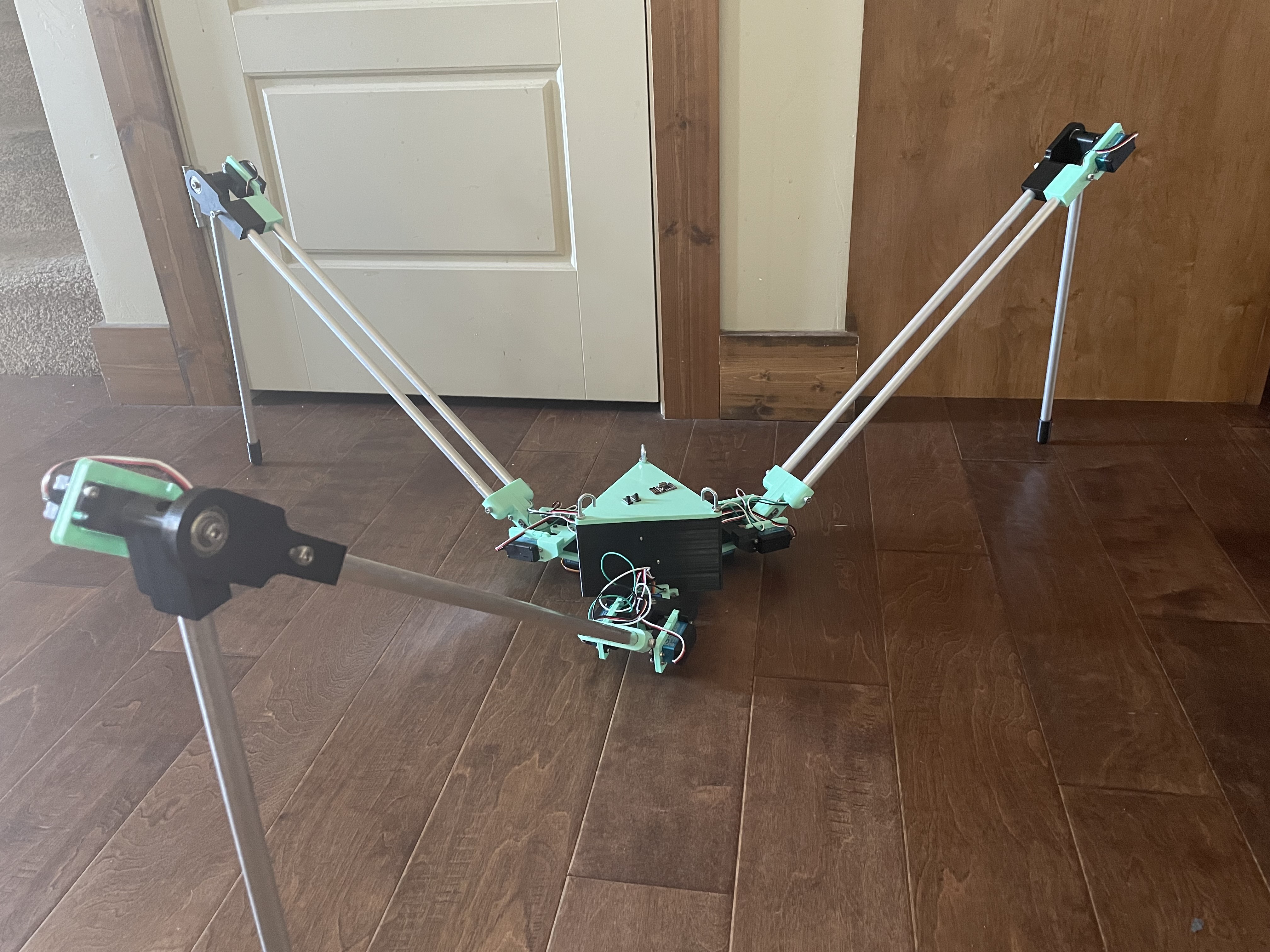
Phase Three - Functional System
As I began phase 3, I ran into some significant problems with the electrical system. Luckily, these problems emphasize a very common problem in most engineering designs. There was too much cohesion between systems and not enough coupling. What does this mean?
Cohesion and coupling are similar, but distinclty different in the way they relate to both software and hardware. In my case, I had two seperate battery packs on the robot, one for the servos and one for the control system. The idea was that these two systems would act as seperate electrical systems but would interact through the PWM signals sent to the servos. This is where I made a fatal mistake. These systems were designed with cohesion, as they shared similar data that relied on information from each system. To be more specific, the PWM signals needed a ground reference in order to measure the signal. Each electrical system had its own ground. This lead to a whole host of problems. Luckily, most of these problems were resolved when the grounds of each system were connected. This made it so all information being shared between systems was reliant on only shared information.
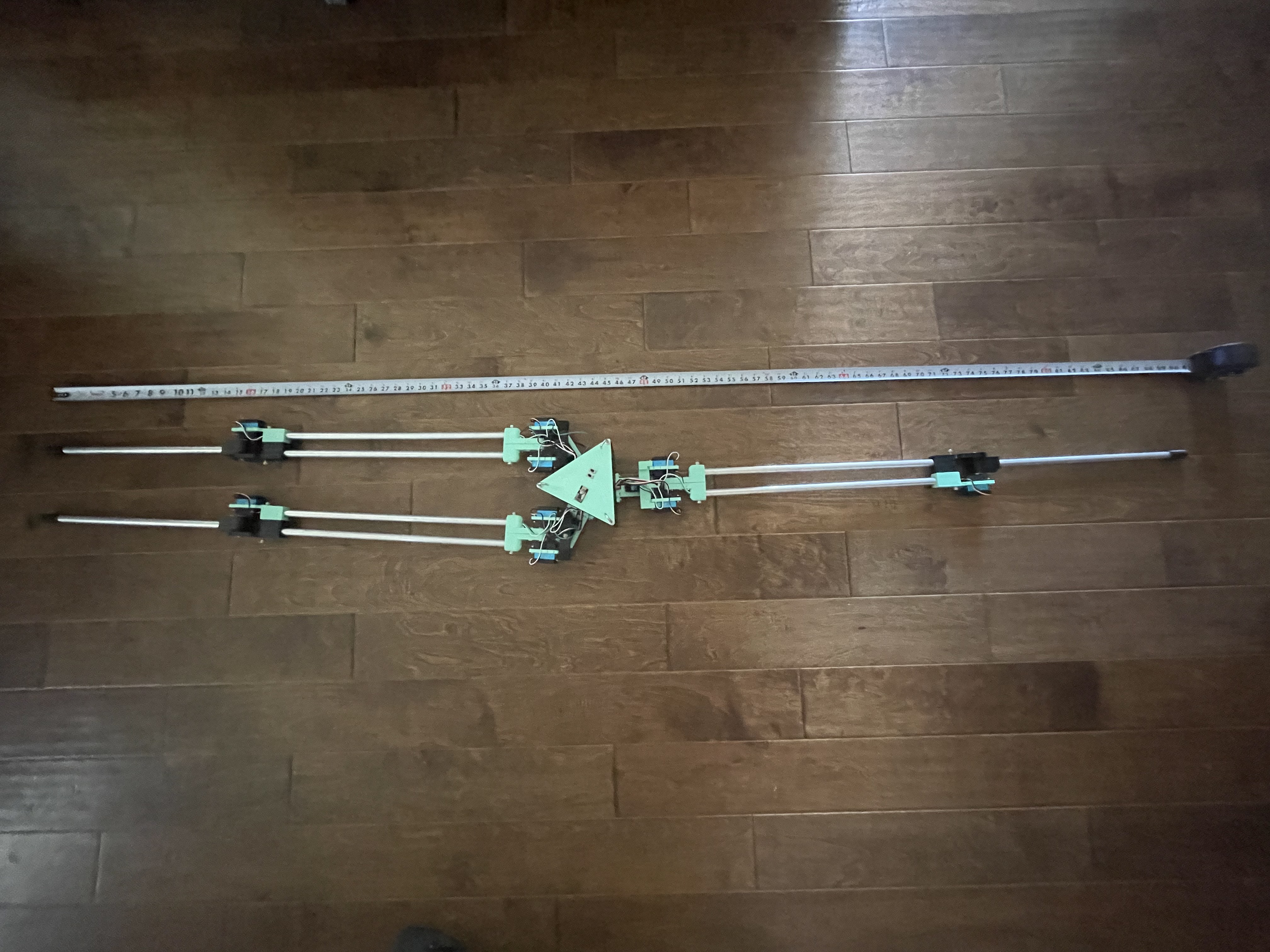
So where are we now? Well, it works! Kind of. The system as a whole is functional, the robot can move on its own, but the servos are currently running at low current, so it isn't very fast. This will likely be solved with a larger battery pack. The size is significantly smaller, at arond 7' 4" when at its longest. This has made it significantly easier to work with. This will likely come down more as the design is refined.
So now what? Well, Phase 4 of course! There are several developments still in the works for this robot, the main one being a redesign of the electrical system to put it onto a PCB. This would sinificantly reduce the size and weight of the main body. Fixing the balance problem is another key issue in the works. A stable control system is also nearly complete! The biggest hurdle however, is the Gait. This may take quite some time to get, but I am confident that the path I am on will lead towards a design that is able to satisfy this requirement.